THM x86 Architecture Overview
Task 1 - Introduction
Because malware works by abusing the way systems are designed, it is essential to know the architecture of the systems they are running in, in order to know how they work.
Learning Objectives
Here are the topics covered in this room:
- Overview of CPU architecture and its components
- Different types of CPU registers and their usage
- Memory layout as viewed by a program
- Stack layout and stack registers
Task 2 - CPU Architecture Overview
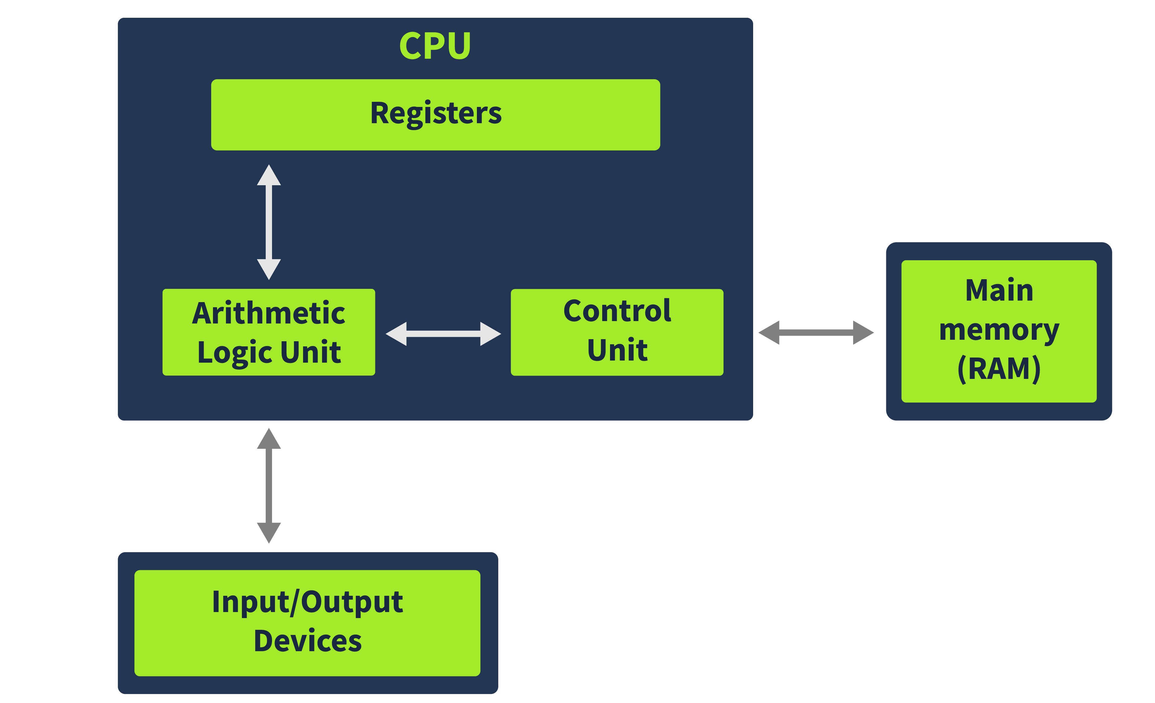
The CPU Architecture that is most widely used is derived from the Von Neumann Architecture.

Von Neumann architecture is composed of three main components:
- CPU (Central Processing Unit):: Executes instructions and controls operations of the computer.
- Main Memory (RAM): Stores data and instructions the CPU needs to operate on. It is where the code and data for a program to run, is located.
- Input/Output Devices: Allows interaction with the computer like keyboards, monitors and storage devices.
The CPU here has three components:
- ALU (Arithmetic Logic Unit): Executes the instructions fetched from memory. Results are then stored in either Registers or Memory.
- Control Unit: Gets instructions from the Main Memory, interprets them to understand what operation needs to be performed, and directs them to the ALU. It also generates control signals to coordinate activities of other parts of the CPU and ensures that instructions are executed in the correct sequence and at the right timing.
- Registers: Registers are CPU’s strorage. While being signifanctly smaller than Main memory, Registers help save time in executing instructions by placing important data in direct access to the CPU. In Registers, there is also a specific register where is located the Instruction Pointer (IP). It holds the memory address of the next instruction to be fetched and executed during the operation of a program. IP is called EIP (Extended Instruction Pointers) in 32-bit and RIP (Register Instruction Pointer) in 64-bit.
In short, when a program has to be executed, it is loaded into the memory. From there, the Control Unit fetches one instruction at a time using the Instruction Pointer Register, and the Arithmetic Logic Unit executes it. The results are stored in either the Registers or the Memory.
Questions
In which part of the Von Neumann architecture are the code and data required for a program to run stored?
Answer: Memory
What part of the CPU stores small amounts of data?
Answer: Registers
In which unit are arithmetic operations performed?
Answer: Arithmetic Logic Unit
Task 3 - Registers Overview
Like said before, registers are the CPU’s storage medium and data can be accessed quickier than from any other memory. However, it’s limited size means it has to be used effectively. For this purpose, registers are divided into the following different types:
- Instruction Pointer
- General Purpose Registers
- Status Flag Registers
- Segment Registers
Instruction Pointer
The Intstruction Pointer or Program Counter is a registers that contains the address of the next instruction to be exeucted by the CPU. It was originally a 16-bit register and was abbreviated as IP. In 32-bit processors, it became a 32-bit register called EIP for Extended Instruction Pointer. In 64-bit systems, this register became a 64-bit register called RIP (the R here stands for register).
General-Purpose Registers
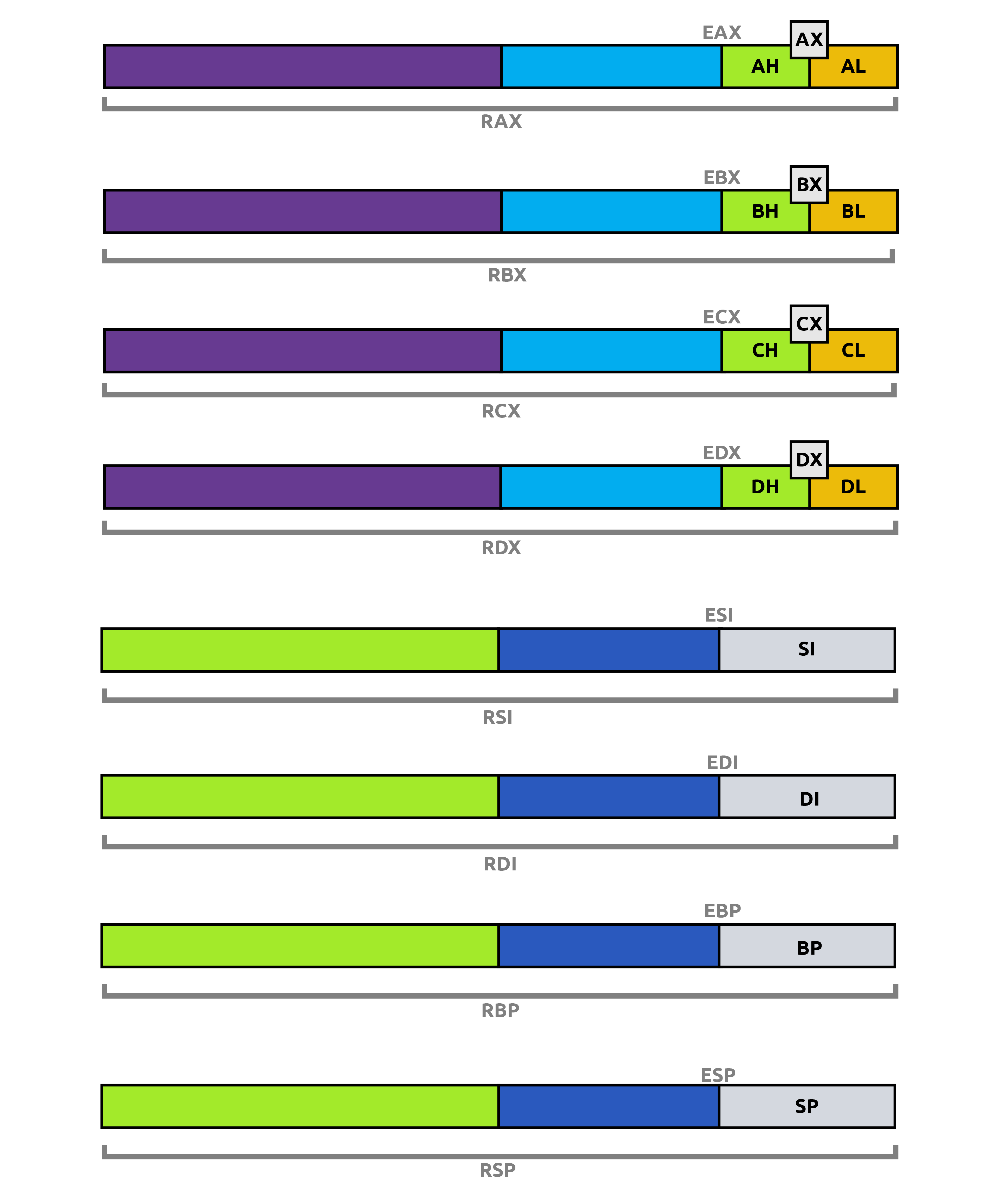
These registers are all 32-bit registers or 64-bit in 64bit systems. They contains:
- EAX/RAX: It is the Accumulator Register. Results of arithmetic operations are often stored in this register. RAX is a 64-bit register and EAX a 32-bit one. The last 16 bits can be accessed by addressing AX. Higher 8 bits can be accessed via AH and lower ones by using AL. These rules also apply to the RBX, RCX and RDX registers, just change the A letter by B, C or D.
- EBX/RBX: This register is also called the Base Register, which is often used to store base addresses in memory operations. Memory addresses are commonly accessed using a combination of a base addess and an offset.
- ECX/RCX: This register is also called the Counter Register and is often used in counting operations such as loops or string operations…
- EDX/RDX: This register is also called the Data Register and is often used in multiplication/division operations.
- ESP/RSP: This register is called the Stack Pointer and holds the memory address of the top of the stack and and is used in conjunction with the Stack Segment register. SS Register, on the other hand, contains the base address of the stack. It is a 32-bit register called ESP in 32-bit systems and a 64-bit register called RSP in 64-bit systems. It cannot be addressed as smaller registers, and this rule is valuable for EBP, ESI and RDI.
- EBP/RBP: This register is called the Base Pointer and is used to serves as a reference point for accessing data within the stack frame using relative offsets. A stack frame is a block of memory allocated on the stack to manage function execution, containing local variables, function parameters, saved registers, and a return address. It is also used in conjunction with the Stack Segment register.
- ESI/RSI: This register is called the Source Index and is used for string operations by holding the source address from where data is read or copied. It is used with the Data Segment register as an offset.
- EDI/RDI: This register is called the destination Index resgister and also used for string operation by holding the destination address where data is written or copied. It is used with the Extra Segment register as an offset.
- R8-R15: These are 64-bit only GP registers and are not present in 32-bit systems. They are also addressable in 32-bit, 16-bit, and 8-bit modes. For example, for the R8 register, we can use R8D for lower 32-bit addressing, R8W for lower 16-bit addressing, and R8B for lower 8-bit addressing. Here, the suffix D stands for Double-word, W stands for Word, and B stands for Byte.
The picture below is the summary of all GP Registers:

Questions
Which register holds the address to the next instruction that is to be executed?
Answer: Instruction Pointer
Which register in a 32-bit system is also called the Counter Register?
Answer: ECX
Which registers from the ones discussed above are not present in a 32-bit system?
Answer: R8-R15
Task 4 - Registers Continued
Status Flag Registers
When performing execution, some indication about the status of the execution is sometimes neccessary. This is where Status Flags come in. In 32-bit systems, this is a single 32-bit register called EFLAGS and in 64-bits ones, this is exetended to 64 bits and called RFLAGS.
- Zero Flag: Denoted by ZF, it indicates when the result of the last executed instruction was zero. In example,
sub rax, rax -> ZF=1. - Cary Flag: Denoted by CF, it indicates when the las executed instruction resulted in a too big or too small number for the destination. In example, 0xFFFFFFFF + 0x00000001 -> CF=1.
- Sign Flag: Denoted by SF, it indicates if the result of an operation is negative or the most significat bit is set to 1.
- Trap Flag: Denoted by TF, it indicates whether the processor is in single-step mode, causing the CPU to execute one instruction at a time.
Segment Registers
Segment Registers are 16-bits registers that divide the memory space into different segment for easier addressing.
- Code Segment: The Code Segment (CS ) register points to the Code section in the memory.
- Data Segment: The Data Segment (DS) register points to the program’s data section in the memory.
- Stack Segment: The Stack Segment (SS) register points to the program’s Stack in the memory.
- Extra Segments (ES, FS, and GS): These extra segment registers point to different data sections. These and the DS register divide the program’s memory into four distinct data sections.
Here is a summary of the different mainly used registers available.
| General Registers | Segment Registers | Status Registers | Instruction Pointer |
|---|---|---|---|
| RAX, EAX, AX, AH, AL | CS | EFLAGS | EIP, RIP |
| RBX, EBX, BX, BH, BL | SS | ||
| RCX, ECX, CX, CH, CL | DS | ||
| RDX, EDX, DX, DH, DL | ES | ||
| RBP, EBP, BP | FS | ||
| RSP, ESP, SP | GS | ||
| RSI, ESI, SI | |||
| RDI, EDI, DI | |||
| R8-R15 |
Questions
Which flag is used by the program to identify if it is being run in a debugger?
Answer: Trap Flag
Which flag will be set when the most significant bit in an operation is set to 1?
Answer: Sign Flag
Which Segment register contains the pointer to the code section in memory?
Answer: Code Segment
Task 5 - Memory Overview
When a program is loaded into the memory of an OS, it sees an abstracted view of memory. This means that the program does not have access to the full memory; instead it only has access to its own memory and for it, it is all the memory it needs to operate. Here, we are looking at the memory as a program sees it.
Memory can be devided into different section, named Stack, Heap, Code and Data.
- Code: This section contains the program’s code. Specifically, this section refers to the text section in a Portable Executable (PE) file, which includes instructions executed by the CPU. This section of memory has execute permissions, meaning that the CPU can execute the data here.
- Data: This section contains initialized data that is constant. This section refers to the data section in a PE file. It often contains global variables and other data that are not supposed to change during the program execution.
- Heap: This section is also known as Dynamic Memory, contains variables and data created and destroyed during program execution. When a variable is created, memory is allocated for that variable at runtime and when that variable is deleted, the memory is freed.
- Stack: This section contains local variables, arguments passed onto the program and the return address of the parent process that called the program. Since the return address is related to the control flow of CPU’s instructions, the stack is often targeted by malware to hijack it.
Questions
When a program is loaded into Memory, does it have a full view of the system memory? Y or N?
Answer: N
Which section of the Memory contains the code?
Answer: Code
Which Memory section contains information related to the program’s control flow?
Answer: Stack
Task 6 - Stack Layout
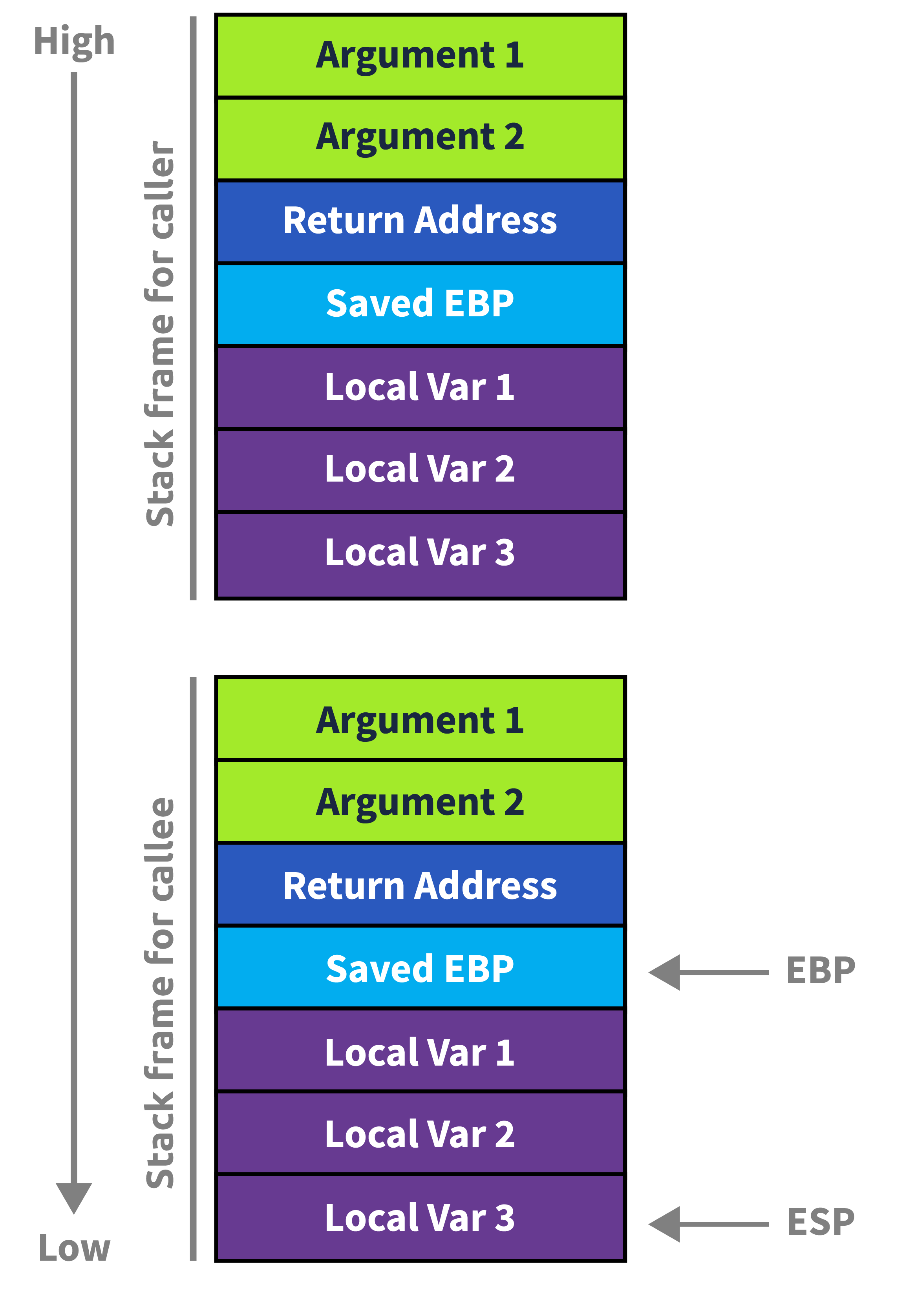
The Stack is a part of a program’s memory that contains the arguments passed to the program, the local variables, and the program’s control flow. This makes the stack very important regarding malware analysis and reverse engineering. Malware often exploits the stack to hijack the control flow of the program.
The stack is a Last In First Out (LIFO) memory. This means the last element pushed onto the stack will be the first one to be popped out.
| Pushed order | Popped order |
|---|---|
| A, B, C | C, B, A |
The two registers to keep track of the stack are the Stack Pointer (ESP/RSP) and Base Pointer (EBP/RBP).
- Stack Pointer: It points to the top of the stack, when any new element is pushed on the stack, the location of the SP changes to consider the new element and does the same thing when an element is popped out.
- Base Pointer: It remains constant for any program. This is the reference address where the current program stack tracks its local variables and arguments.
- Arguments: Arguments being passed to a function are pushed to the stack before the function starts execution. These arguments are present right below the Return Address on the stack.
Old Base Pointer and Return Address
Below the BP lies the old Base Pointer of the program that calls the current program and below the oBP lies the Return Address, where the Instruction Pointer will return once the current program’s execution ends.
A common technique to hijack the control flow is to overflow a local variable on the stack such that it overwrites the Return Address ith an address of the malware author’s choice. This technique is called a Stack Buffer Overflow.
Function Prologue and Epilogue
When a function is called, the stack is prepared for the function to be executed. This means that the arguments are pushed to the stack before the function execution. After that, Return Address and old Base Pointer are pushed onto the stack. Once these elements are pushed, the Base Pointer is pushed into the stack. As the function executes, the Stack Pointer, which pointed to BP, now moves as the requirement of the function. This portion of code is called the Function Prologue.
Similarly, the oBP is pushed into the BP when the function exits. The Return Address is pushed into the Instruction Pointer and the Stack pointer is rearranged to point to the top of the stack. This portion of code is called the Function Epilogue.

Question
Follow the instructions in the attached static site and find the flag. What is the flag?
Copy the Stack Diagram.
Answer THM{SMASHED_THE_STACK}
Task 7 - Conclusion
In this room, we explored the fundamental components of x86 CPU architecture, including the Von Neumann model, CPU components such as ALU and Control Unit, various types of registers, memory layout, and the organization of the stack.
Understanding these concepts is crucial for analyzing malware behavior and gaining insights into system operations. By grasping the role of registers, memory sections, and stack layout, one can delve deeper into computer architecture and enhance their skills in cybersecurity and reverse engineering.
Enjoy Reading This Article?
Here are some more articles you might like to read next: